Winter Break
I have a month between semesters at Austin Community College. Time to work on the last project in a series!
As usual, more photos at Flickr. https://www.flickr.com/photos/aneel/albums/72177720315236826/ and https://www.flickr.com/photos/aneel/albums/72177720326943829/
When we remodeled our bathroom, we bought a slab of pretty quartzite for the counter. The counter only needed part of it, but you have to buy the whole slab and we didn’t want it to go to waste. We had the counter folks cut the remainder into useful sizes and I’ve been slowly making steel table bases for them.
As my fabrication skills have improved, the bases have gotten more complex.
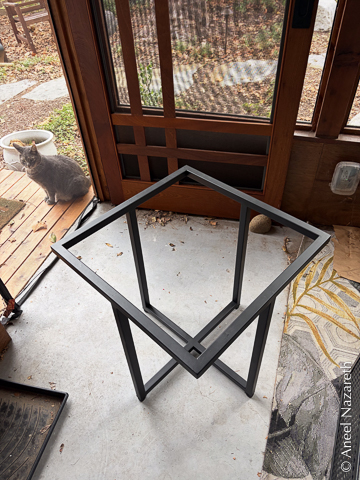
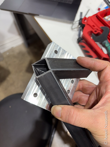
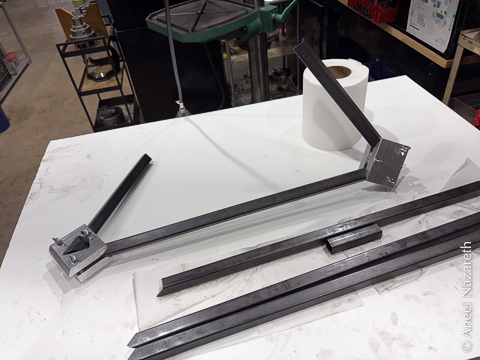
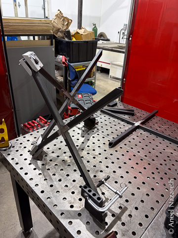
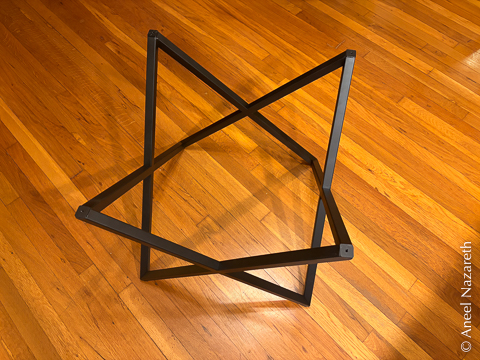
For the last of the table tops, I decided on a design with four X shapes around the outside. All of the angles in the two similarly-sized tables were either 45° or 90°. The same is true for the angles on these sides… if you hold the pieces at a 45° angle while cutting them. That’s a bit tricky on a conventional saw.

No problem! I just spent 6 months in a machinist apprentice program. I can do this on the mill! How hard could it be?
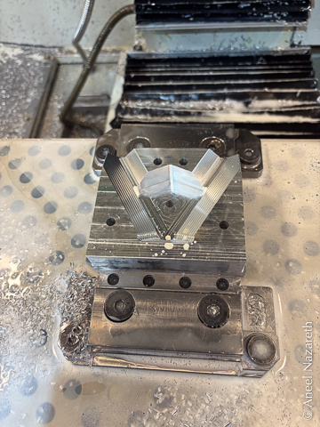
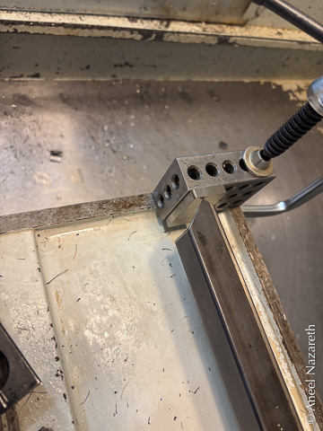
Cutting the corners actually wasn’t too bad, though I did learn some (expensive) lessons about how endmills react to the sudden pressure changes and vibrations involved in milling tube (by shattering). But I did some test corners and they fit together well on the fixture table. On to the welding!
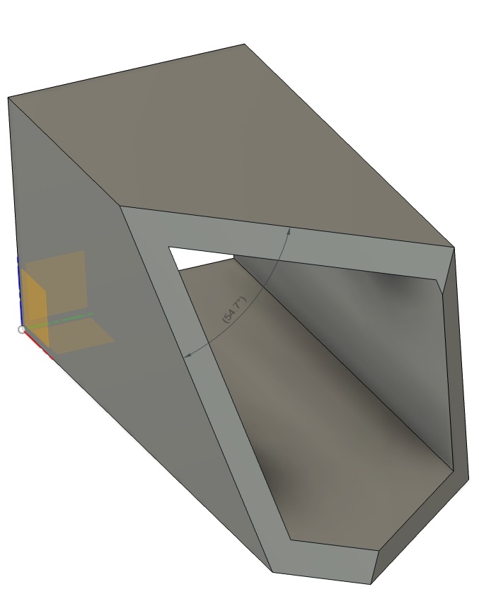
Wait, what do you meant the joint that I want to weld is exactly where that fixture block is. No, of course I can’t weld the exposed angle. That’s the one everyone is going to see and filing it back to that crisp edge after welding it would take forever. Surely I can make a jig that lets me clamp that joint from the other side. Let me just 3D print up a model…
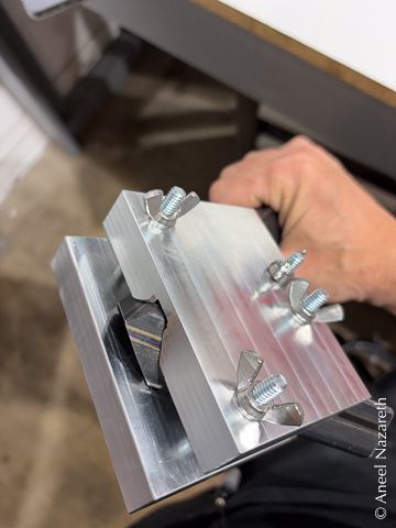
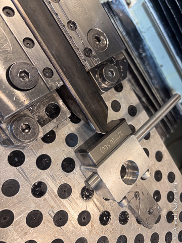
I can’t weld against a plastic jig, of course, so I just need to make that in metal… Hmm. But getting end mills in at those angles is exactly the “you need to hold it at 45°” problem. Let’s figure out how to do this flat… Hmm. Going to need to order some new shapes of endmill… And for clamping, we might as well just use a two-sided jig with bolts instead of trying to get F clamps in at those angles…
(Weeks of messing with tool paths later) Yessss, that should do the trick.
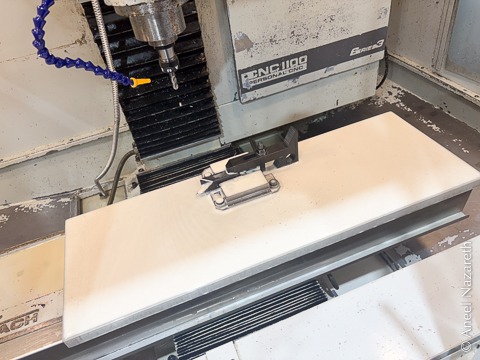
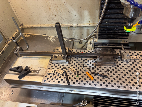
We’re ready to prep all of the parts. Hmm. these parts are longer than the travel of the CNC mill. No problem, we’ll just figure out some creative fixturing and do it one end at a time.
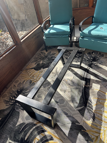
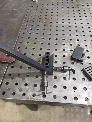
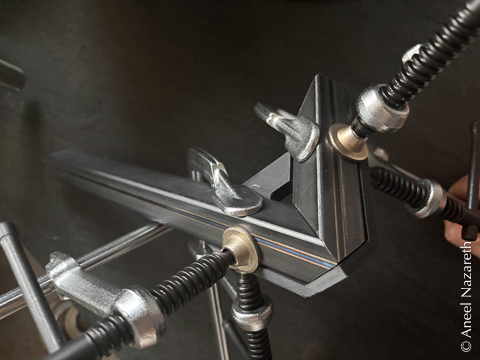
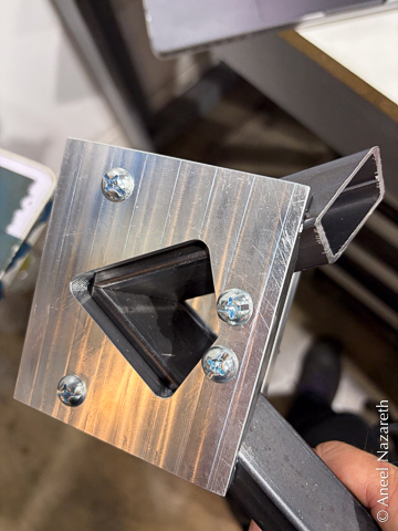
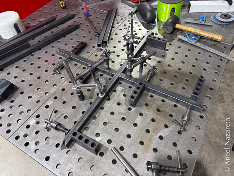
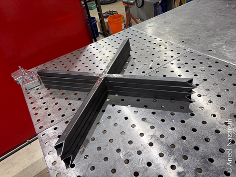
Finally welding time! First let’s make the X parts. Just the kind of thing a fixture table is for…
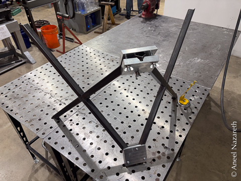
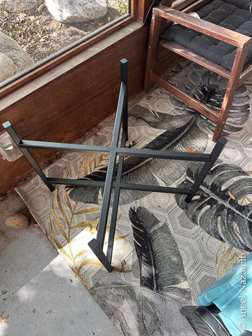
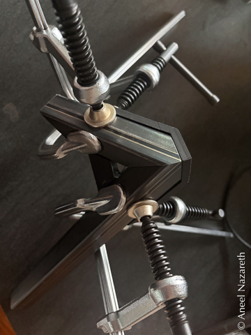
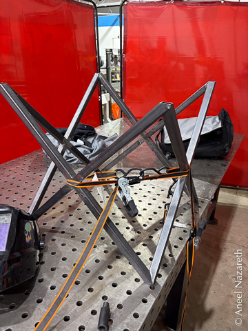
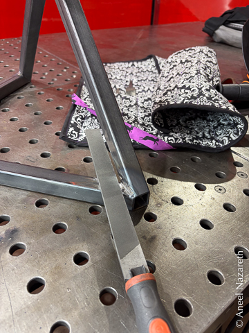
And the tricky part: welding using the custom jigs. It went well for three of the four sides. The fourth needed some “encouragement” from some ratchet straps to come together. It didn’t take too much filing to bring the interior 90° corners up to the necessary level of finish. Much easier than filing at 54.7 degrees!
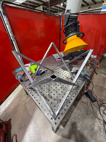
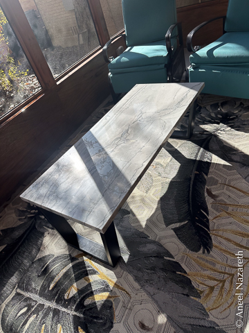
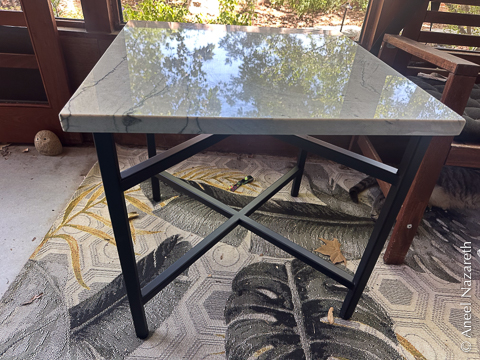
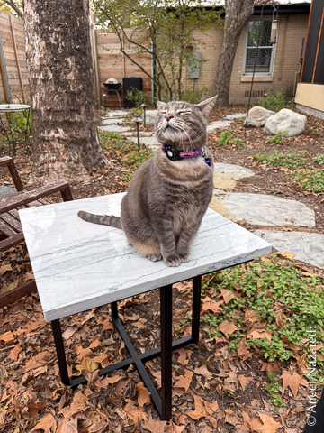
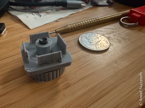
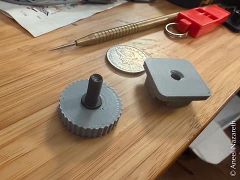
One tricky thing is that the 1” tubing leveling feet that I have don’t fit into the corners of these. So let’s model up some custom ones and 3D print them. All that’s left is a few coats of flat black paint, leveling feet, and the final quartzite tabletop. Finished! Or almost.
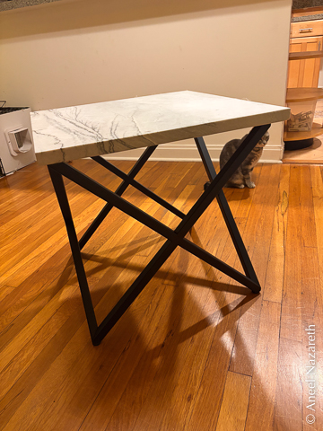
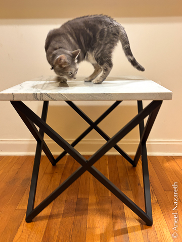
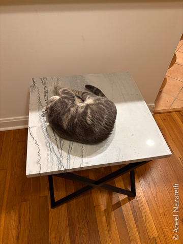
Final quality assurance check? Passed! #cat