Advanced Fabrication
Well, I totally failed to keep up with this journal during the semester, and this class was most of the reason why. Advanced Layout & Fabrication is a capstone class in the Architectural and Ornamental Metal program. I was hesitant to take any other classes at the same time, because I could see myself sinking a huge amount of time into this one. I fortuitously messed up my registration, so I ended up taking only one other class, which worked out well.
As usual, more and larger photos on Flickr: Advanced Fabrication WLDG-2435
The class is project based. Each student pitches something to the teacher, who acts like a “client”. We produce sketches, then full-sized plans, material lists, cost estimates, schedules, prototypes and samples for the “client” to evaluate. If all of that gets the nod, we try to build the actual thing.
I pitched building a front door. The project is supposed to have repeated elements, and our entryway already has a cephalopod theme, so the door would have a tentacle motif. Because I’m a glutton for punishment, I decided to make a “Dutch” door, where there top and bottom panels swing independently so that our cats don’t escape when we open the door. And, because it seemed like a good idea, I designed the door to have a thermal barrier layer rather than letting the metal transmit temperature changes from the outside in.
My professor accepted the pitch and told me that he was looking forward to having me in the class again next semester.
I spent the first few weeks sketching the door and then building a detailed 3D model, including all of the layers, fasteners, etc.
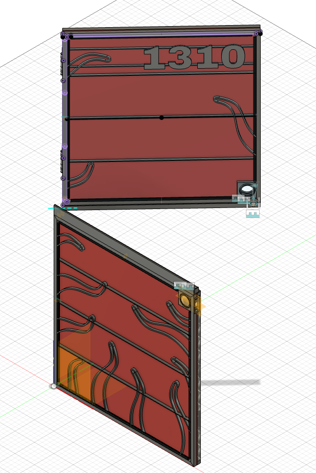
Tentacles
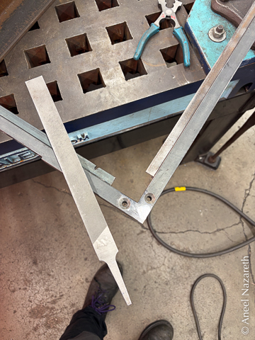
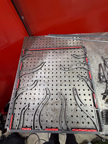
There were a lot of complicated parts of the design, but I started out by focusing on the repeated elements. I had designed the tentacle elements so that, while they had a lot of variation in length and positioning, they were all based on a single S-curve.
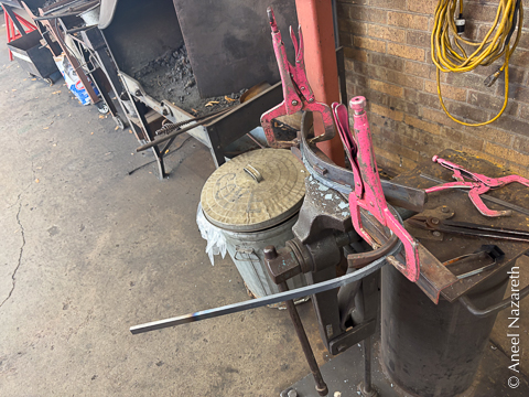
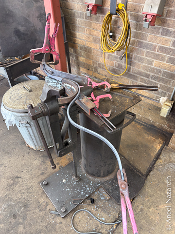
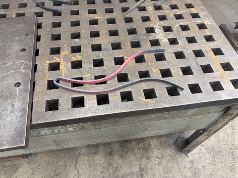
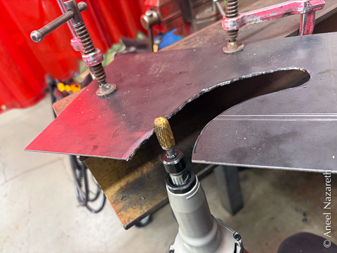
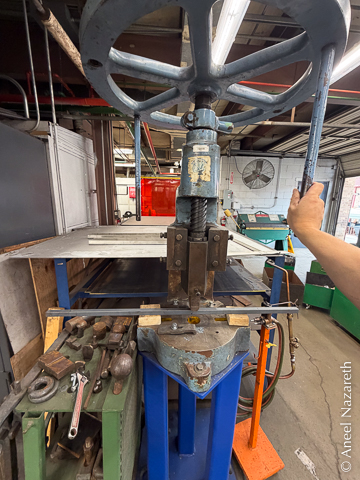
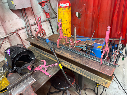
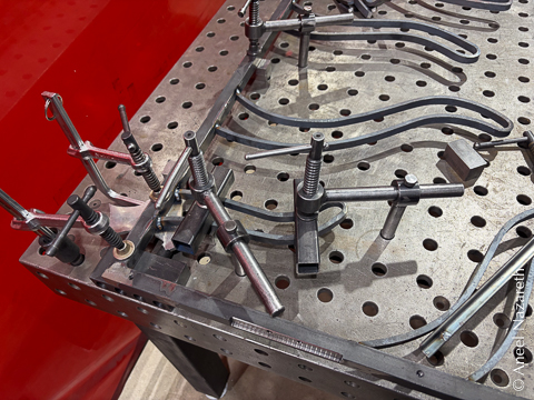
I used the fly press to make a two-piece “castle” jig. Like the crenellations of a castle wall, there are two levels to the jig. First the taller piece is used to bend one radius of the S-curve, then the piece is dropped to bend the reverse curve with the shorter piece. If the two pieces were the same height, the jig for the second bend would be in the way of the first bend.
I used my old friend, the fly press, to bend the basic curves. Then I welded the pieces together.
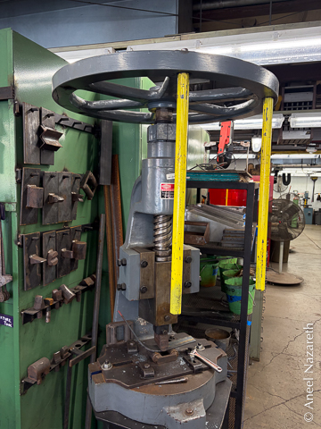
The jig ended up working quite well. I’d heat a steel bar in the forge, and bring it over to the jig. I’d use a large vise grip to clamp the hot bar on the far end, and then pull the bar into the curve. A second vise grip would lock in the bend. Then I’d remove both of those clamps, lower the piece an inch, reapply the first clamp, and pull the bar into the second curve. Finally, another clamp would lock in the second curve.
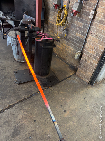
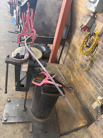
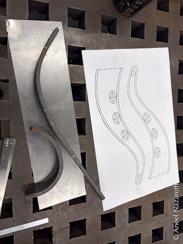
The bar is then taken back to the forge and the process is repeated on the other side to create a wavy bar (not an Ω shape, why would you mention that?). One key thing that I needed to work out was the length of the bar that would make the curves line up properly since I bent from the ends of the bar towards the middle (29”, if you’re curious).
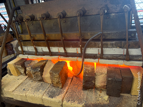
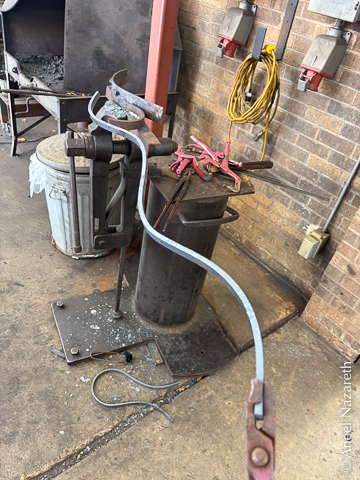
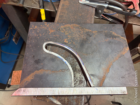
To turn the double S into a tentacle, a single extra bend is made at the middle of the bar. I used induction forge to heat just that area. I made a jig with a couple of pins to do this bend, but I found it easier to just bend it by hand. The great thing about the induction forge is that the heat is isolated enough that you can hold the two ends in your bare hands and bend the middle. I don’t have any pictures of this because of my limited number of hands.
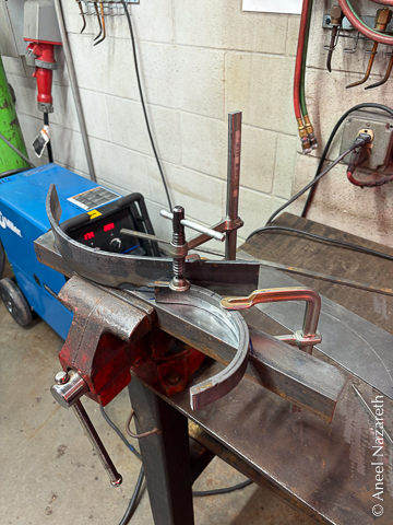
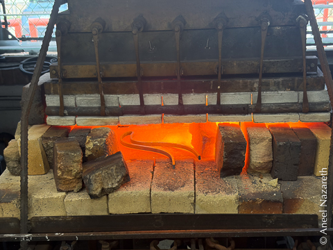
All of this bending is basically impossible to align perfectly, but the tentacles need to be planar to fit the sheet metal properly. To remove any twists, I took them back to the forge, got them good and hot, and then set a heavy plate on them.
Prototyping
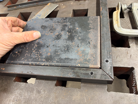
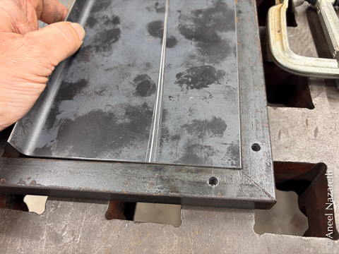
To check the techniques needed for the overall project, I made a sample piece. I mocked up a corner of the bar I’d use for the frame and tested which corner style I liked for the sheet metal. I wanted the finished piece to show the frame, and I didn’t like the slightly rolled corner of the folded inset version. So the flush inset version won out.
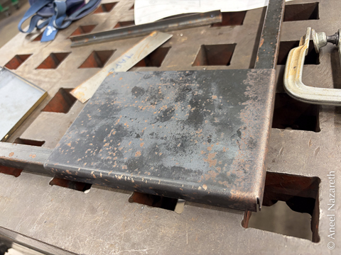
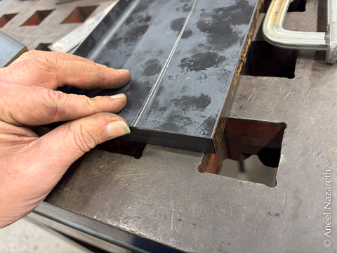
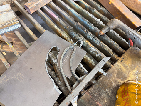
Next, I tested setting a tentacle into the sheet. I welded in a short tentacle sample to a piece of bar. I roughed out the shape with a plasma cutter and used a die grinder and dynafile to clean up the edges.
Finally, an angle iron shelf is welded to the bar to support the double-sided tape that will hold the sheet metal in place. The result looks good. But it’s important to not get cocky, there’s a lot of work to go…
Frames
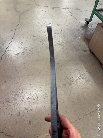
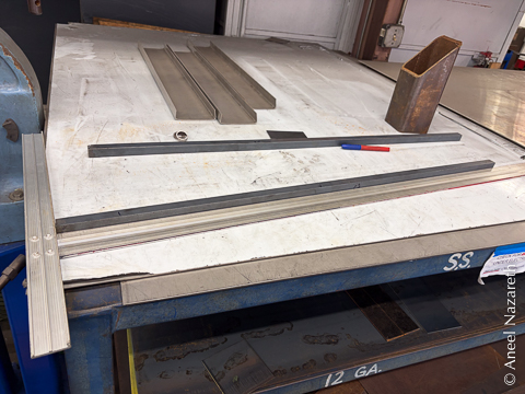
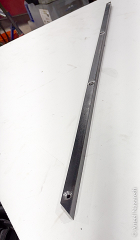
In order for the door to fit well in a door frame, the nearly-square frames of the panels need to match precisely. The first task is to straighten the .75” bar. You might think that steel fresh from the mill would be straight. It is not.
I used a large framer’s T-square as a straightedge to figure out where the bar deviated and then used a fly press to make small bends until I was happy with the alignment in each plane. I hoped there wasn’t much twist in the bars, because that would have been much harder to fix.
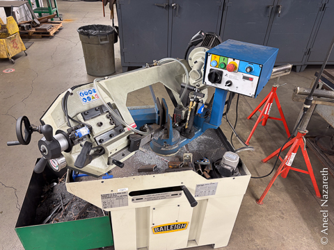
I cut the bars to length and mitered them using a horizontal bandsaw. I spent a lot of time trying to get a perfect 45° miter, but could have been less precise on this (foreshadowing!). This is done by making a cut you hope is right and then hold the two pieces so they form a corner. You use a square to check if they make a perfect 90° by looking for gaps on the legs of the square that let light through. If you see light, you figure out which direction to adjust the saw, and try to not overshoot. Unfortunately, I didn’t have any really trustworthy squares available. I should have brought a machinist’s square in from home.
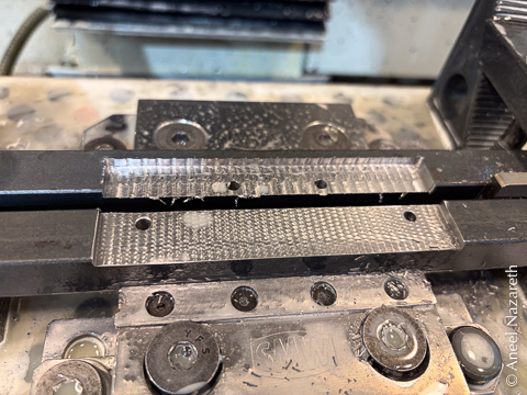
Rather than welding the two faces of the door to each other, the plan was to use bolts. In the most ridiculous gesture in this project so far, I opted to use a CNC milling machine as a glorified drill press to drill and countersink the holes for the bolts, which go all the way through the inner frame and halfway into the outer frame so they are not visible on the outside of the door. The CNC mill lets me be sure I get the depths uniform, but just using a drill press would have been much, much faster because the mill doesn’t have enough travel to do the whole bar at once, so it needs to be repositioned in the middle. The important thing is not the absolute placement of the holes, just that they match the ones on the corresponding frame and aren’t off by enough to look weird.
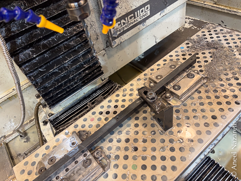
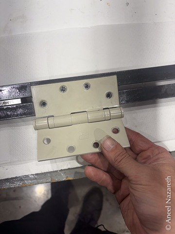
But there are good reasons to use a CNC mill for some of this: the recesses for the hinge and the doorknob/lock box need to be cut, and this is quite difficult using other techniques. Oh, and while we’re doing that, we might as well machine the miters to be exactly 45°. So much time wasted trying to dial in that bandsaw…
While the frames of the door panels would be made of bar stock, the panels themselves would be made of sheet. But how to attach them? Welding them using traditional processes (MIG or TIG) would introduce a lot of heat and cause the sheet metal to warp. Instead, the plan was to attach small angle iron (0.5”) shelves to the frames with a small number of welds and use very strong tape to attach the sheet metal to the shelves.
It was finally time to weld each frame together. One of the challenges of welding is distortion caused by heat. Welding introduces enough heat to melt metal, so it can cause warping, and then as the weld cools it wants to contract, which introduces further warping. To counteract this, I fully constructed the frame, so that the bolts and the other panel would anchor the places I was welding. More importantly, I used “counterposed” welds, moving quickly through a sequence of welds that oppose each other as they cool.
There was one corner where I had trimmed the bars too much, and there was a slight gap. I tacked one face and then welded in a shim to fill the gap.
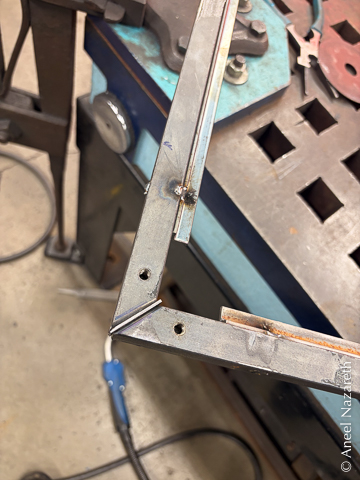
After tacking (two tacks on one face, one on the other), these welds were ground flat. They looked good, so the next task was welding it out, making a complete bead from the inside corner to the outside corner. These welds were then ground flat. Finally, the corner edges from the front face to the back face were welded out. The inside corners were never welded. Once everything was fully welded, it was all cleaned up one more time with an angle grinder and then fine-tuned with a file.
Sheet Metal Back
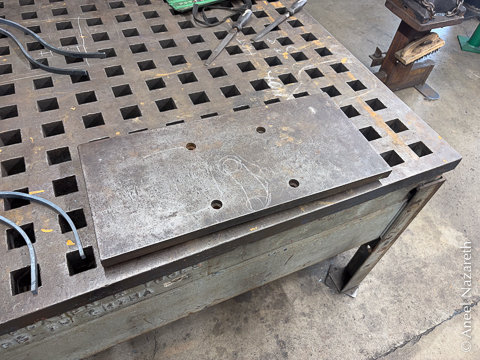
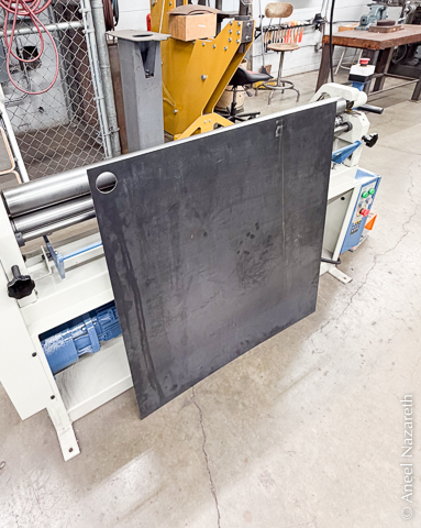
I mentioned earlier that the faces of the door would be sheet metal. One of them was pretty simple, just a sheet of 16 gauge (~1/16th”) steel in a rectangle, with a circular hole. Easy, right?
I cut the sheet with the big hydraulic sheet metal shear, which — happily — is back online. It was out of commission when I took Intermediate Layout, and we did all of the straight shearing with a stomp shear, cutting with body weight. Doing that for 16 gauge steel would have been really pushing it.
The hardest part of the shearing process was making sure the cuts were square to the edges of the frame. I couldn’t use the squaring guide along the side of the shear, because who knows how square it is? Also, maybe my frame isn’t perfectly square itself. It’s more important that the sheet matches it than that the sheet is itself square. In the end, this involved a lot of sighting scribed lines transferred from the frame along the blade of the shear.
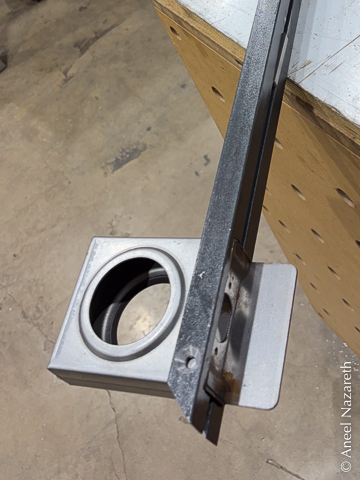
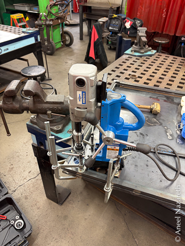
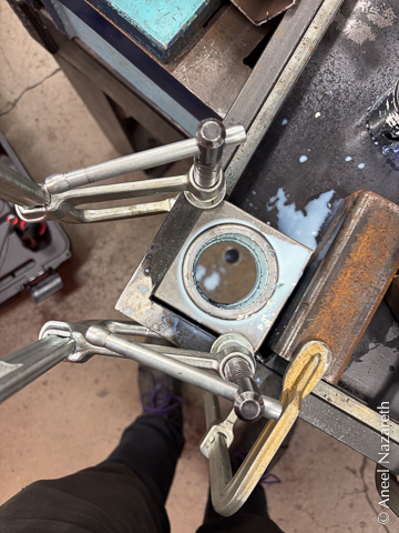
The other cut in the back side is the circular cutout for the doorknob. I made this cut by putting the weld-in lockbox in place to establish the location of the hole, and then using a mag drill to make a straight cut using a hole saw. This was a fairly ridiculous operation because the drill didn’t have enough clearance for it to sit flat on the sheet. The whole point of a magnetic drill is that you can position it on the thing you want to drill, turn the magnet on, and know that it will stay aligned as you drill. I ended up clamping supports to the sheet, magnetizing the drill to those, and drilling down through the lock box. Needless to say, a different technique was used for the other sheet.
After the cutting, it was important that that sheet actually be flat. I did this with a sheet metal roller. I used this tool a lot in the lamp project in Intermediate Layout & Fabrication, but we’re not trying to get a cylinder or cone here, just a flat sheet. It took about half an hour of running it back and forth through the roller, tweaking the settings slightly each time, to get it flat throughout.
Tentacle Placement
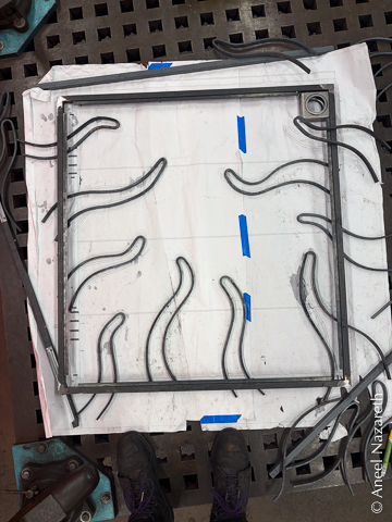
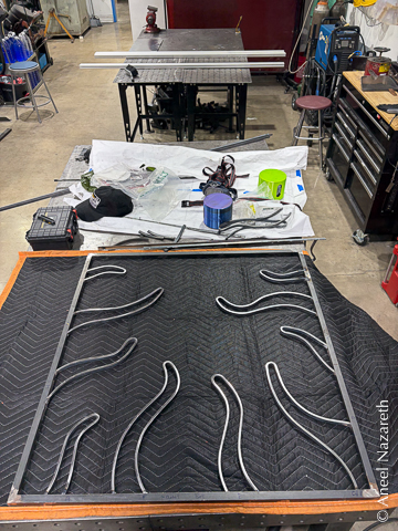
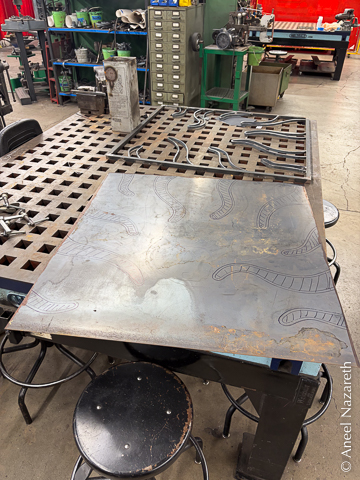
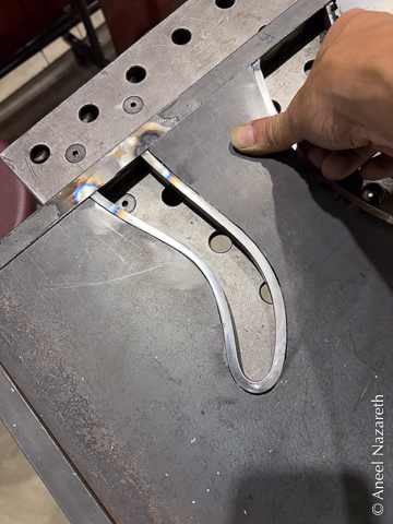
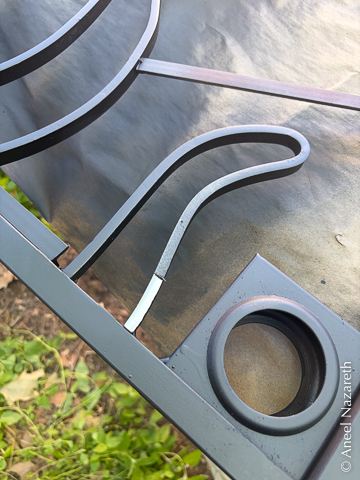
The other sheet metal panel was far less straightforward. For starters, it could only be fabricated once the exact shapes and placements of the tentacles were established. Time to weld them in!
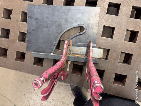
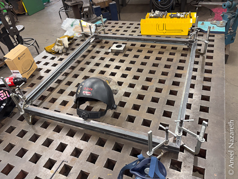
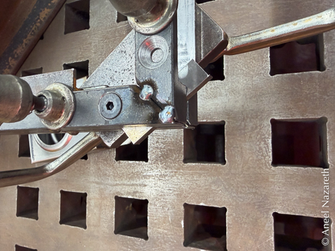
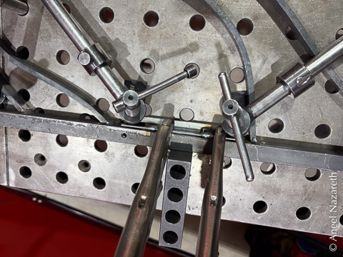
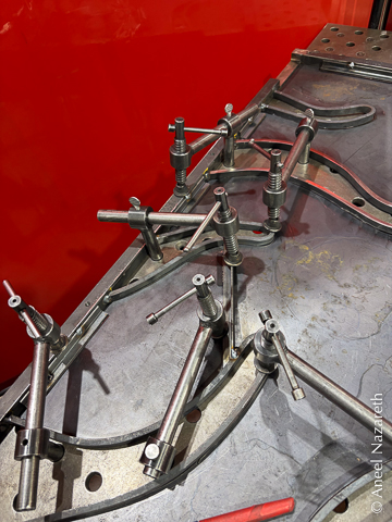
The tricky part welding them was again planarity. Welding oddly shaped pieces of metal to the frame would result in weird forces as the metal cooled, and any deviation from the plane would be noticeable. I took advantage of Asmbly’s fixture table for this. This table was one of the reasons I joined Asmbly in the first place, and I talked about it in one of my furniture projects. The table is a (reasonably) flat surface with a grid of holes every two inches that you can put fixtures in. In this case, I mostly used clamps. This let me secure the frame flat and then hold each tentacle securely against the flat surface while the welds cooled, hopefully freezing them flat. It worked pretty well.
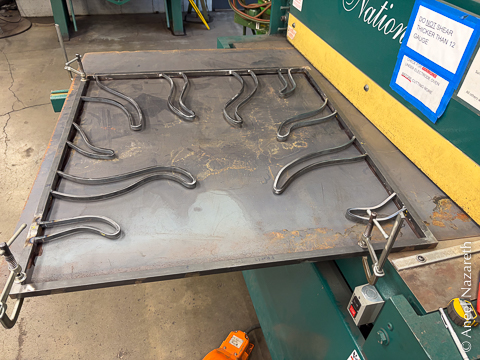
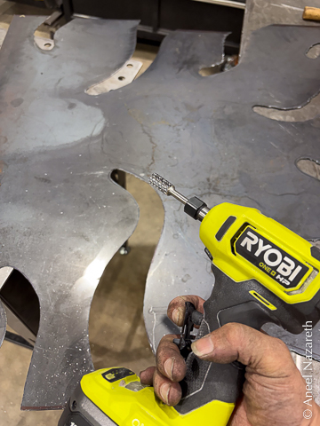
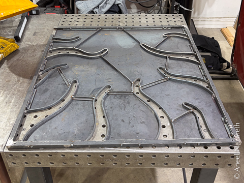
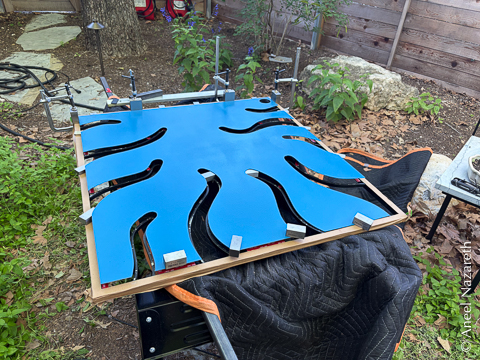
With the tentacles placed, the front sheet could be sheared. Then the tentacles were roughly traced on the sheet.
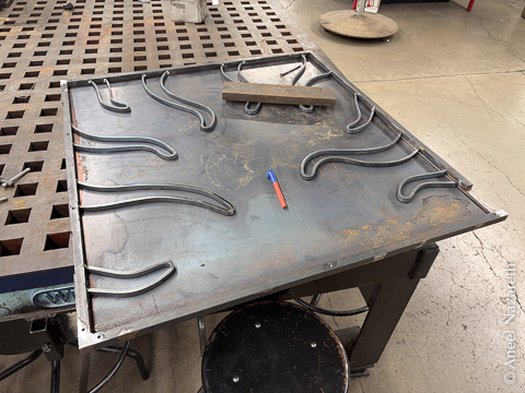
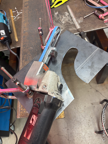
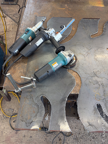
I experimented with various ways of cutting out the tentacle shapes in the prototyping phase. Of the tools at ACC, only the plasma cutter could reasonably do the job. Freehand plasma cutting a big sheet of metal was pretty nerve-wracking, since there’s essentially no easy way to fix any mistakes. But at least it’s fast! It took less than an hour to rough out the shapes.
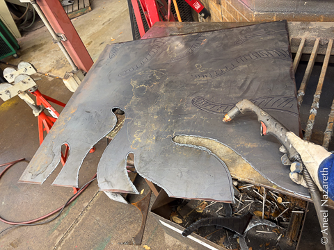
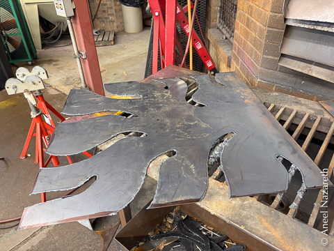
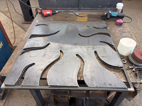
Fine-tuning the fit was nowhere near as quick. Over several long days at ACC and Asmbly, I worked to get the sheet to drop in cleanly around the tentacles, using die grinders, dynafiles (essentially finger-sized belt grinders), and the trusty angle grinders and files. A lot of the tuning could be done by working down to the traced outlines, but for the final fitting, I had to resort to repeatedly lifting up an edge, removing some material, and trying to fit it again. By far the most dangerous tool to use was the die grinder. It could very quickly remove too much material!
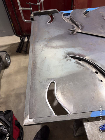
Like the back, the sheet metal was to be mounted with tape, so shelves needed to be welded in. Segments were welded around the edges, using the fixture table clamps to hold them down and vise grips to hold them to the frame. It wasn’t possible to roll this sheet flat because of all of the cuts, so instead, I installed cross-braces between the tentacles in places where I noticed they tended to buckle.
On this side, I skipped the mag drill for installing the lock box and just used a handheld drill with the hole saw. Much easier, and the flange of the doorknob will cover the edge and hide any slight misalignment.
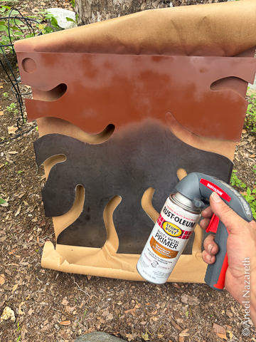
Painting
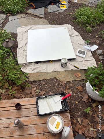
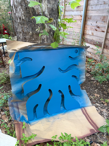
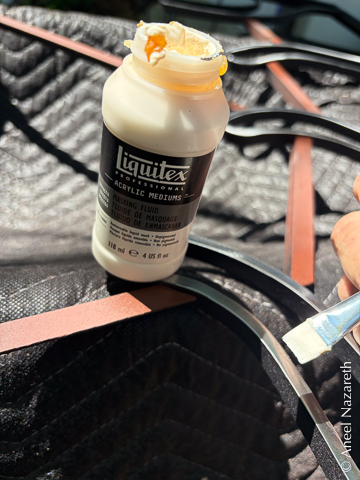
Painting is my least favorite part of metal projects. I made life a little easier for myself this time by buying a “comfort grip” handle for the rattle cans, which was actually quite a bit more comfortable. I started with two coats of rusty metal primer. After rollering on a coat of house paint, I decided to get a paint sprayer. Definitely worth it. There was lots of touching up, sanding back, respraying, etc., but I’ll spare you the play-by-play.
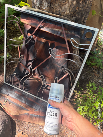
The tentacle side of the frame was again more complex. I wanted the steel tentacles to show, but not rust, so I first polished the primer off of them with angle grinder scotch brite discs and then sprayed it with clearcoat. I masked that clearcoat with liquid latex. I then used black spray paint to finish the rest of the frame. Finally, I peeled off the latex mask… which mostly worked.
Taping
The final critical step was taping the sheets to the shelves on the frame. This is almost as nerve-wracking as plasma cutting because the tape is very sticky and it’s basically impossible to reposition once it has made contact. I enlisted my partner’s help. We did the easy, rectangular side first, and got it almost right on the first try. After a few days of stewing over it, I ended up cutting the tape through the middle and peeling it all off. Then I filed down the edges of the sheet so that I was really sure it would drop in perfectly. Lesson learned, I made sure the fit was as good as possible for the tentacle side.
Unlike the flat side, it was not a simple matter of making sure two corners were correct and then slowly lowering the panel down. The panel itself was slightly floppy, and a bow would be a problem. I ended up using my magnetic shim set to suspend the sheet above the frame, with increasing thicknesses of shim as I went. We aligned the sheet, and started pulling out shims in pairs. After each pair, we’d make sure the sheet was still aligned properly. We did a test run before exposing the tape and then did it for real. Amazingly, it worked!
Final Result
The door was almost too big for the backdrop for the final photos, so please excuse the tight crop!
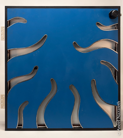
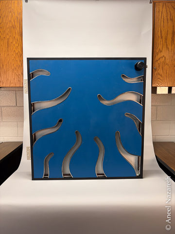
How’d it turn out? Well, the real treasure is the lessons we learned along the way! I think it looks great for a prototype, and I feel ready to tackle the top panel in the fall. I’m definitely hoping to change up the approach a bit…