Maker Chip Challenge
Watching youtube videos, I came across the idea of a “Maker Chip”, which is a poker chip-sized token that shows off your skills and acts as a calling card. They’re apparently popular items to hand out at 3D printing conventions.
It occurred to me that it would be a fun to have a contest at Asmbly to make these things. Not just using the 3D printers, but all of the different tools and skills in use at Asmbly. I proposed the idea, and got general buy in… and discovered that it had been a few years since anyone ran a contest at Asmbly and there wasn’t really an established way to do it.
So I took it on myself to run the contest.
Here’s the forum post kicking it off: Maker Chip Challenge! End-of-summer contest!
We ended up getting 16 entries, which seems like a pretty good turnout. Some of them are really spectacular: Maker Chip Challenge Entries and Voting!
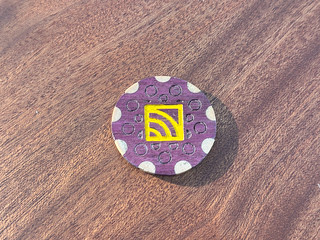
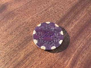
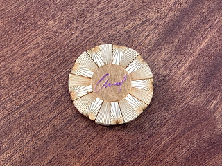
Of course, I didn’t even try to resist the temptation to make my own entries. I made a chip in every shop. I modeled my chips on a Sonic “Free Medium Drink” chip that I happened to have around, with an edge pattern with nine pairs of stripes. Each ship has the logo for the shop on one side and my signature on the other.
I started out designing them all in Fusion, but switched over to Affinity Designer for some of them by the end.
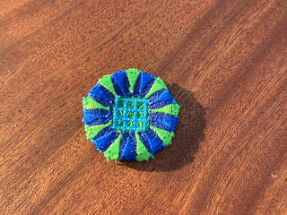
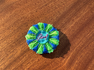
3D Printing
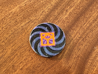
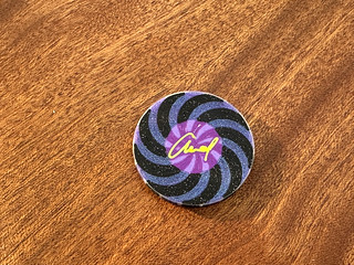
This is the shop that I’m the lead of, so I had to do something complicated for this. I ended up doing a 7 filament print: the two major colors for the striped edge (in this chip, it’s a spiral), the logo color (orange) and my signature color (bright green). When the spirals enter the logo/signature area, they change color. I discovered that the joins between the stripe colors had an ugly raised seam, so I added an outer perimeter of translucent PLA to give them a nice edge.
The challenge here is that Asmbly has multi-filament printers, but they can’t handle 7 filaments. Luckily, two of my filaments don’t share a layer, so I could put in a layer-based filament change. But that still leaves me with 6 filaments on the first and last layers. One of the extruders on the 5 filament printer is currently not aligned with the other 4, so I needed to do something extra.
I started out trying to do repeated prints without taking the previous print off of the bed, but that ended up causing problems during bed leveling, because the leveling test would bump into the already-printed material
Evan mentioned another approach: you can tell PrusaSlicer that your printer has more extruders than it actually does. Then when you generate the gcode for your print, you can edit it to change tool changes to those extra extruders into something else. I wrote a perl script to add an M600 filament change command and remap the tool number to a tool that actually exists.
Metal Shop
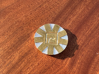
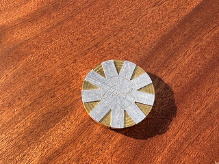
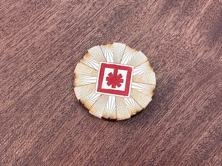
Since I am taking a machining class, I decided to do my metal chip on the Tormach. My biggest challenge here was work holding. To have a two-colored edge, I would need to use two materials (aluminum and brass), and each of them would have to extend the whole height of the chip and fit together. This meant machining both front and back of each piece.
Machining the front was easy enough. I could just hold a square piece of stock in the vise. But the front and back needed to align, so when I flipped the piece over it would need to be locatable. Also, I was going to cut around the whole edge of the part, so the vise wouldn’t have a flat edge to grip at the end.
My first attempt was to make a fixture that would function as vise jaws and locating pins in one.
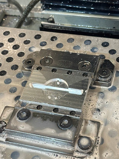
The round edges would act as jaws making contact with the whole circumference of the part, and the pins would fit into the empty triangular shapes to keep the piece aligned.
Unfortunately, clamping on that 3mm edge didn’t provide a strong enough hold to prevent the piece from being pulled up into the end mill.
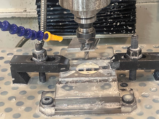
Next, I tried the tape + glue method. I’ve used this on the wood CNC routers, and everyone said it should work on the Tormach as well. The idea is that you put painter’s tape on both the stock and a sacrificial piece and super glue the two together. I could not get this to hold. My machining teacher suggested using double-sided carpet tape instead, but that didn’t hold either.
After talking with my teacher, I discovered that I was making three mistakes.
- I was trying to do facing cuts with a 3/8” end mill to avoid having to do a lot of material removal with a 1/8”. The cuts were too aggressive
- I was cutting too deep. I thought 0.020” was safe, but 0.010” was a better maximum
- I was using coolant, which was weakening the bond
When I fixed those, the carpet tape worked pretty well. I used two 0.250” bores to locate the part when I flipped it over. By boring the same holes into the sacrificial support and using two end mill shanks as gauge pins, I could line up the second side without re-probing X and Y.
Once I could hold the piece in place I wasted a few parts getting the heights right for engraving. Telling Fusion to engrave the edges of the logo resulted in a cut that was way too deep. so I ended up setting the heights manually well above the part and creeping up on them.
The other trick was those pointy wedge corners where the two parts join. They’re easy to machine on the “positive” side, where the wedge material is still there, but on the “negative” side, it’s impossible to use a round mill to get a sharp triangular point. I had expected to use the set of jeweler’s files that I’d just bought for my other class, but that didn’t work as well as I’d hoped. What did work well was a jeweler’s saw.
This was also my first time using brass on a CNC mill (I’ve done a lathe project, but not a mill project). It went beautifully, giving a good surface finish on the first try. This might be because I sprang for the expensive “360 Free Machining Brass”.
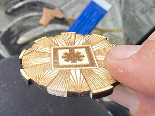
Woodshop
My initial idea for the wood chip was fairly similar to the metal one: two different materials, cut into negatives of each other using CNC, then sandwiched together. After a few tries on the Laguna iQ, I realized that there was no way I’d get the tolerances I needed. 40mm diameter doesn’t leave much room for error!
Happily, the circular motif that I had chosen was well-suited to another option: dowels. I did the edge cuts all the way through, engraved the rest of the circles on the surface, and used dowels of a different wood to fill the edge cuts.
This had the happy side effect of having built-in fixturing. The dowels were the locating pins when I flipped the piece over. I intended to mill right through them on the second side, but the side load was stronger than 3mm of glue could resist and they just popped out, so I ended up using flush cut saws to clean them up.
I tried a bunch of different wood combinations, but the wood I ended up liking the best was purpleheart, so I chose the lightest colored dowels I had picked up at Woodcraft to provide contrast.
This was my first time using 1mm end mills. I bought a 5 pack and was surprised to have 3 still intact at the end of the project!
Textiles
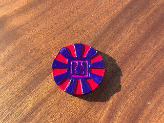
I’ve been trying to get the hang of the embroidery machine, and this project gave me lots of practice. My first challenge was figuring out the Affinity Designer → Inkscape → Ink/Stitch workflow. Inkscape’s UI is foreign enough to me that all of my actual graphics work happened in Affinity Designer. Figuring out the right options in Ink/Stitch was a lot of trial and error.
There was a careful balance between adding layers of stitching to stabilize the fabric (you can see some of the wrinkling around my signature) and taking them away to prevent the design from becoming too thick. It seemed like beyond ~4 layers, the bobbin thread would get pulled up to the front. I fiddled with the thread tension a lot, but it was challenging to avoid any white on the front. Maybe it would have been worth winding bobbins to match the top thread. Along the way, a screw disappeared inside of the bobbin case, so I attempted my first ever sewing machine repair… we ended up just replacing the part, though.
I also found that I got much better results with new thread. Asmbly has a lot of donated thread, but it’s unclear how long it has been sitting around.
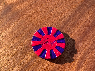
Once I’d machine embroidered both sides, I had to hand stitch them together. I tried using embroidery floss, but the machine embroidery thread looked better. The only problem was the number of stitches to get a solid border. I tried doubling up the thread, but it led to knots, so I fell back on my usual hand stitch. Which turns out to be doubled! I had no idea that people typically don’t tie the ends of their threads together after passing it through the needle. What I’d been trying was probably quadrupling it.
Electronics
This one was a journey.
The poker chip form factor is a real challenge for electronics, not because of the 40mm diameter, but because of the 3mm thickness. Even coin cell batteries are pushing it, unless you do without a holder. So I decided not to try putting power on the chip itself, and instead opted to use a wireless charging coil. This meant that the chip would be inert until you put it on its stand, which is kind of cool on its own.
What should it do? I went with the old standby: blinkenlights. I did a prototype with an Adafruit Gemma M0 and a NeoPixel ring and it worked great. I had to turn down the brightness on the NeoPixels because the coils max out at ~500mA, but still got decently bright results. All done, right?
Not quite. The Gemma has two problems: it’s too thick, and it doesn’t have enough LEDs. I could desolder some of the taller components (the LiPo battery connector and the USB Micro port), but even the switches are a bit too tall. And the RGB LEDs are tall enough that layering them on top of the board or the coil would be a no-go. There’s also the small matter of the circuit for the charging coil, which is thin, but not that thin.
So I decided to do something I hadn’t tried since the days of etch-it-yourself copper boards and make a circuit board. Adafruit is a huge supporter of Open Source Hardware so the schematic for the Gemma M0 is freely available. I opened it up in Fusion Electronics (a first for me) and got to work stripping out everything I didn’t think I needed (foreshadowing).
The board that gets power from the coil was… less well documented. I was able to read the T3168 label on the IC and found a data sheet that looked plausible… in (I think) Chinese. I found some other references that looked similar so… I guessed at a couple of the values, hoping I’d end up with something that worked. I jammed the two circuits together and asked on Asmbly’s forums if it seemed reasonable.
I started laying out the board. I spent a bunch of time on Digikey, choosing particular parts based on how thick they were. I tried to get a design that put all of the power and logic on one side and the LEDs on the other, but that was just too thick with the 5050 Neopixel LEDs. Moving the LEDs to the same side created space problems. Luckily, I mentioned this to another Asmbly member, Steve, who pointed out that I could get smaller LEDs. I briefly looked at 2020s, but ended up jumping all the way down to 1010s.
I do not have the confidence in my soldering skills to do a 32 pin surface mount microcontroller, so I decided to get the boards pick-and-placed as well. This led to me trying to find the components I’d found in Digikey’s catalog (generally including thicknesses) in JLCPCB’s part catalog. Of course there were lots of cases where they didn’t have the exact thing, and didn’t list the thickness of their equivalent, so I had to go through the data sheets for each part and find the packaging specs.
After submitting the design, I discovered that a bunch of that work was wasted, because JLCPCB freely substituted other parts with the same footprint. I had to go through several cycles of “no, that won’t work, it’s too thick”, and ended up having to give up on pick-and-placing everything and source some of the critical components from elsewhere. Ironically, this included the T3168 power regulator for the coil, whose data sheet I’d originally found on JLCPCB’s website. I ended up getting some diodes from Digikey and ordered the T3168 from two separate sellers on AliExpress and one on eBay, just in case.
Having pulled the trigger on the order, I discovered that I was going to get hit with a 55% tariff on it, but I was too far down this road to be deterred.
Several weeks later, a box arrived with 5 boards. Remember how I took all of the chunky connectors out of the design? I’d planned to use pogo pin clips to connect to the contacts that I’d put on the board. This would have worked great, except that I got the wrong pitch of clips. Steve helped me build a fixture that let me hook up to the board and supply power and everything.
But, of course, the board didn’t do anything. Because the microcontroller on it was unprogrammed. I thought I’d read all of the Adafruit tutorials that I needed about getting software onto it, but things were just not working. The programmer would connect, it would write the bootloader, it would verify the bootloader, and then nothing.
I knew by this point that I’d made a mistake on the board. The schematic for the Gemma M0 says that the microcontroller is a SAMD21E, but if you look at other docs you discover that it’s actually a SAMD21E18A. I’d chosen the first SAMD21E in JLCPCB’s catalog, which was a SAMD21E17D. Oops. Saliently, the 17 series has half as much flash storage as the 18 series. But no big deal, I wasn’t going to write a complex program, right? Just blink some lights…
I spent days learning how to debug a microcontroller, single-stepped through the code, found the problem to be a memcpy call failing, started a thread on the Adafruit forums about it, tore out my hair in frustration, finally had it suggested that I try basing my bootloader config off of the only 17 board in the repo, rather than off of the Gemma’s. Lo and behold, there was a config “`
// This is needed because SAMD21E17A only has 128kB of flash
#define FLASH_NUM_ROWS 512
Building with this option worked! The green status LED I’d put on the back of the board lit up! The USB drive showed up on my computer! All I needed to do was build CircuitPython for my new board and I could start making fancy patterns…
Memory region         Used Size  Region Size  %age Used
FLASH_BOOTLOADER:           0 B         8 KB      0.00%
  FLASH_FIRMWARE:      184156 B      57088 B    322.58%
FLASH_FILESYSTEM:           0 B        64 KB      0.00%
    FLASH_CONFIG:           0 B          0 B
       FLASH_NVM:           0 B        256 B      0.00%
             RAM:        6848 B        16 KB     41.80%
Yeah, CircuitPython itself is 140% of the size of the Flash on my chip. Oops.
At this point, I resigned myself to coding in C. But how? I could have done it in the bootloader codebase, since I’d already single-stepped through a bunch of it to find that memcpy error, but it seemed more civilized to not mix bootloader and light flasher, so I set out to learn enough about the Arduino IDE to write a “sketch”.
This turned into another config problem because I had to define my custom board to make it a valid compilation target in the IDE, but I muddled through that. The tricky part was actually loading the code. I thought my bootloader was compatible with what Arduino expected, but I couldn’t get the IDE to find it. I ended up using the “Export Compiled Binary” and then using gdb to load that binary over a connection through the hardware debugger, rather than the USB interface.
Finally, the lights blinked!
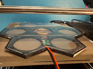
The 3D print for the housing for this was actually a bit interesting. I ended up using the PET sheet trick from Modern Gridfinity Case by Matthew to create a transparent layer so that the chips can be viewed from either side, and I ended up printing the power transmission PCB into the frame itself, rather than make some kind of door.
After some testing to make sure that the coils were close enough through the PET sheet for effective power transfer, I discovered another fun surprise: the PET had started puckering because the Maker Chip runs too hot. I’m not sure if this is waste heat from the inductive coil being badly tuned (remember those values I just guessed?) or just the power dissipation of 10 RGBLEDs in a small space or what.
Anyway, a journey, as I said.
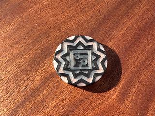
Ceramics
When I was a kid, a friend of the family had a pottery studio where he ran classes. So I have some history with clay. But I basically didn’t touch it for decades until taking 3D Design last semester. Happily, Winnie was able to give me some pointers, and I used some of the techniques from the Maker’s Mark curriculum that I once hoped to make into an Asmbly class.
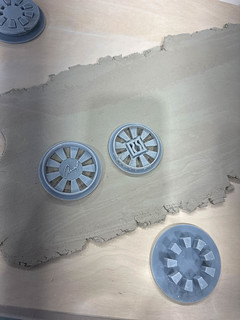
My ceramics chip was made with resin printed cookie cutters/pattern stamps. I quickly realized that I had to make a set that made impressions on both sides simultaneously, because otherwise the second stamp would smoosh the first. And I also found out that I had to support the first stamp while stamping the second. And that I had to press out the resulting piece with even force. So this ended up being a 4 part assemblage of 3D printed parts. That took a few tries to get right.
I thought that Asmbly had a twice-a-week firing schedule, so when I submitted my pieces for firing on 9/22, I thought I’d be fine as long as they didn’t shatter in the kiln (very possible!). But I checked mid week and found them still on the shelf, so I grabbed one in its “bone dry” state and brought it home to paint. Happily, it came out okay. I’m curious to see how they fired…
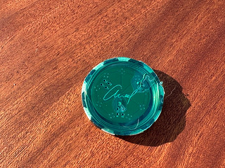
Lasers
I ordered a bunch of fancy 2x2 samples of acrylic from Houston Acrylics. Multi-color, multi-layer, fun finishes. But with two days to go in the challenge before I started working on Lasers at all, I grabbed some 1/8” ply from the scrap cart, cut my design, and called it good.
One fun thing about this was getting the alternating color edge. I did this by extending half of the spokes like a gear and then trimming them off. So the laser burn is the dark color and the light color is saw cut. This was also handy for registering the parts as I flipped them.
Conclusion
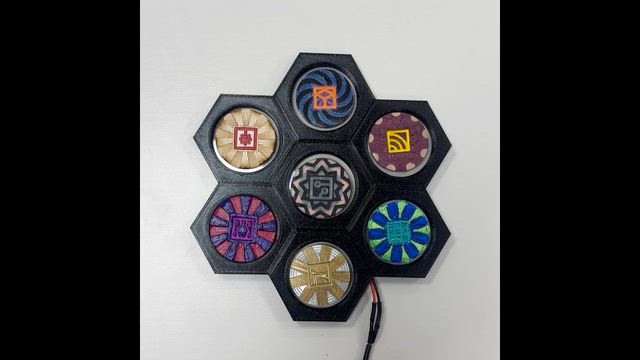
Here’s a video of the finished set in its holder.
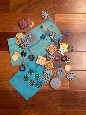
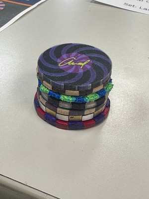
Some of the prototypes that I went through, and the finished chips stacked to show their striped edges.
I had a lot of fun, a lot of frustration, and learned a ton in this challenge. I’m happy I did it. I’m also happy that it’s over. Deadlines can be very helpful sometimes.